mr_byte31
Hero Member

 Offline Offline
Posts: 604
Thank You
-Given: 75
-Receive: 144
|
 |
« on: July 02, 2024, 05:56:34 17:56 » |
|
Hi Folks, I have a digital laser signal (red color) with max frequency 1 MHz so I decided to use a phototransistor instead of photodiode since phototransistors have higher gain. I checked the application notes from OSRAM but I only found the below configurations. 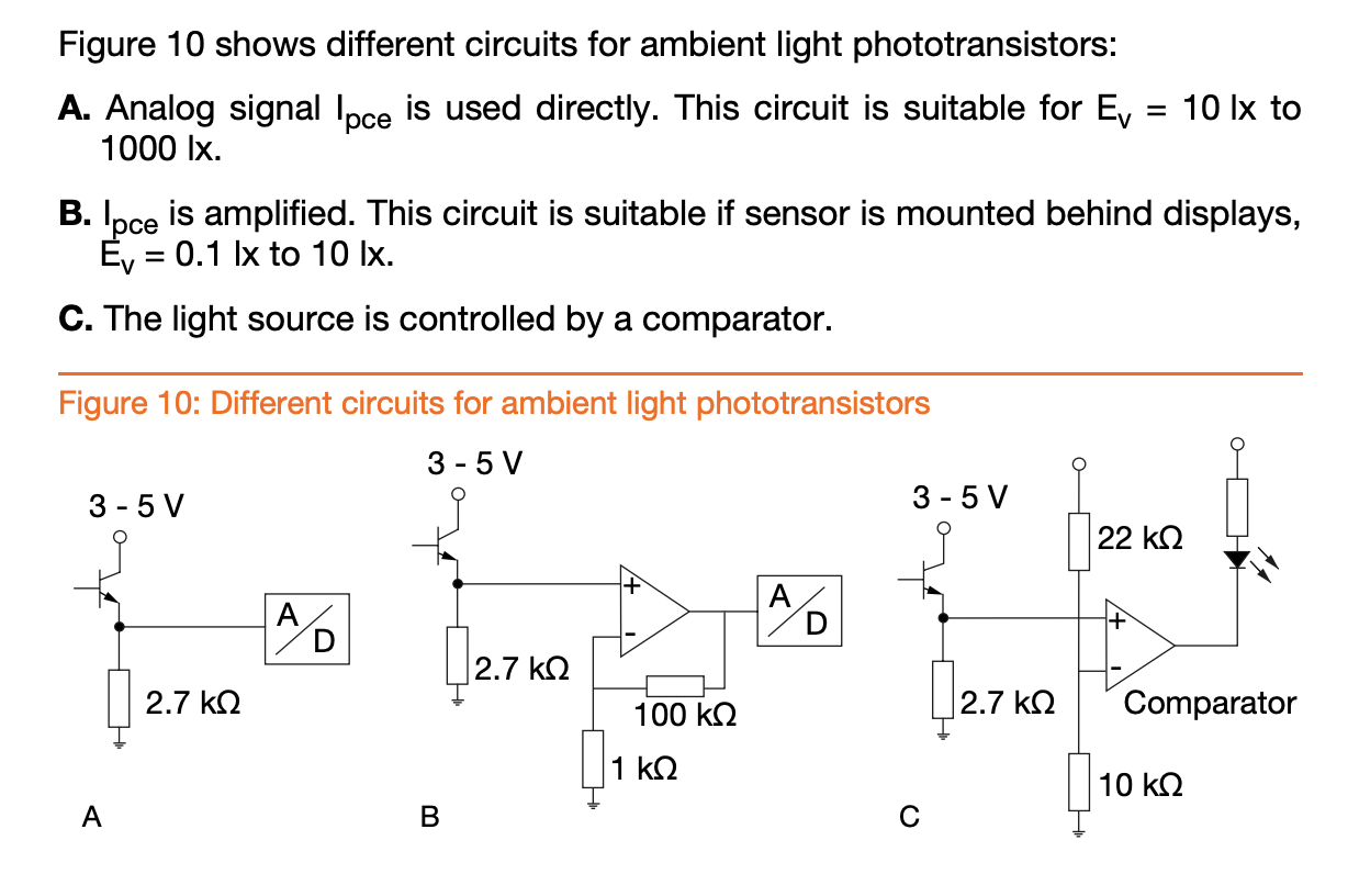 option B, looks like non-inverting amplifier. I want to design a transimpedance amplifier for my phototransistor SFH-3410--just phototransistor instead of the photodiode in the figure.  in the datasheet , the max V_ce=5.5v and max collector current = 20mA I see that the phototransistor will be connected to V_b and virtual ground ( negative terminal of the op-amp). shall I put V_b as 5.5v ? I am just afraid if the laser intensity is large enough, it would allow more current than 20 mA and burn the phototransistor. |
|
|
|
« Last Edit: July 02, 2024, 05:58:35 17:58 by mr_byte31 »
|
 Logged
|
Do not trifle with the Moderators , as you are small, and crunchy, and taste good with ketchup.
|
|
|
PM3295
Senior Member
Offline
Posts: 317
Thank You
-Given: 365
-Receive: 157
|
|
« Reply #1 on: July 03, 2024, 12:39:35 00:39 » |
|
You can try the circuit below. It appears through simulation the JFET current source should be fast enough for operation at 1 MHz. Of course, this should be verified during prototype testing.
VS1 should be lowered to 5 V to accommodate the specific photo transistor. The other supply for this opamp must be higher than 5 V since the maximum output swing will be about 2 V from the supply rails.
|
|
|
|
« Last Edit: July 03, 2024, 12:55:16 00:55 by PM3295 »
|
Logged
|
|
|
|
mr_byte31
Hero Member
Offline
Posts: 604
Thank You
-Given: 75
-Receive: 144
|
|
« Reply #2 on: July 03, 2024, 10:17:41 10:17 » |
|
Many thanks bro.
This is definitely a good idea to use JFET as current source to ensure maximum limit.
I just have few questions
1- Vout swing from -1.5v to -4.6v this is because of the DC offset bias in the OP-Amp ?
2- from your experience, what would be the maximum freq for the phototransistors ? I couldn't find anything in the datasheet about rise or fall times !
3- any reason to use a JFET ? would a MOSFET be an alternative solution ?
|
|
|
|
|
Logged
|
Do not trifle with the Moderators , as you are small, and crunchy, and taste good with ketchup.
|
|
|
PM3295
Senior Member
Offline
Posts: 317
Thank You
-Given: 365
-Receive: 157
|
|
« Reply #3 on: July 04, 2024, 05:22:41 05:22 » |
|
I just have few questions
1- Vout swing from -1.5v to -4.6v this is because of the DC offset bias in the OP-Amp ?
2- from your experience, what would be the maximum freq for the phototransistors ? I couldn't find anything in the datasheet about rise or fall times !
3- any reason to use a JFET ? would a MOSFET be an alternative solution ?
1/ The op-amp output can't get closer than about 2 V from the supply rails as per datasheet. https://www.analog.com/media/en/technical-documentation/data-sheets/AD8001.pdf2/ Photo transistors are normally quite slow in comparison to photo diodes. Typical rise-fall times for photo transistors will be in the region of several us, compared to sub us times for photo diodes as shown in the datasheets. https://ams-osram.com/search?productSearch=true&filter_products=phototransistorshttps://ams-osram.com/search?productSearch=true&filter_products=photodiodes3/ With MOSFETs you have to deal with the gate capacitance and other internal capacitance's, which will tend to make the transient response too slow for your proposed 1 MHz pulse rate. You can try and run some simulations, and most probably find that you have a problem dealing with large overshoot of current spikes. The JFET is a simple solution with very low gate capacitance. You can make a similar fast current source with bipolar transistors, but is a bit more complicated and simulation shows that the current pulses from the JFET solution looks cleaner. It is interesting to note just how slow a dedicated current regulator such as the LM334 will be at higher frequencies. The last plot shows the performance at only 100 kHz. |
|
|
|
« Last Edit: July 04, 2024, 07:16:31 19:16 by PM3295 »
|
Logged
|
|
|
|
mr_byte31
Hero Member
Offline
Posts: 604
Thank You
-Given: 75
-Receive: 144
|
|
« Reply #4 on: July 04, 2024, 09:01:42 09:01 » |
|
may I ask , what tool do you use for simulation ?
|
|
|
|
|
Logged
|
Do not trifle with the Moderators , as you are small, and crunchy, and taste good with ketchup.
|
|
|
Sideshow Bob
Cracking Team
Hero Member
Offline
Posts: 1077
Thank You
-Given: 238
-Receive: 1051
|
|
« Reply #5 on: July 04, 2024, 10:50:41 10:50 » |
|
Another thing, Take precautions to not allow any opamp (also the internal one in the AD) to get saturated by the signal. From an opamp perspective. It takes ages to get out of saturation. This may not show up in the simulation
|
|
|
|
|
Logged
|
I have come here to chew bubblegum and kick ass... and I'm all out of bubblegum
|
|
|
PM3295
Senior Member
Offline
Posts: 317
Thank You
-Given: 365
-Receive: 157
|
|
« Reply #6 on: July 04, 2024, 03:13:39 15:13 » |
|
I use several programs depending on the models and features available: Tina Pro TopSpice Simetrix I also use LTSpice, Proteus and Orcad to a lesser degree. For RF work, it will be ADS, MWO(Cadence) and Ansys. I love the very old version 3 of Ansoft Designer as well. TopSpice and Simetrix can do gain-phase analysis of switching model in analyzing switching converters. Most other programs you will need to use average steady-state models (which are not always available) to do the same thing. There are ways to create your own models, but it takes a long time to set up correctly. Another thing, Take precautions to not allow any opamp (also the internal one in the AD) to get saturated by the signal. From an opamp perspective. It takes ages to get out of saturation. This may not show up in the simulation
"A traditional voltage-feedback amplifier, lightly loaded, has a slew rate limited by the current available to charge and discharge the internal compensation capacitance. When the input is subjected to a large transient, the input stage will saturate and only its tail current is available to charge or discharge the compensation node. With a current-feedback amplifier, the low-impedance input allows higher transient currents to flow into the amplifier as needed."https://www.analog.com/en/resources/analog-dialogue/articles/current-feedback-amplifiers-1.html |
|
|
|
« Last Edit: July 04, 2024, 07:33:39 19:33 by PM3295 »
|
Logged
|
|
|
|
optikon
Cracking Team
Hero Member
Offline
Posts: 861
Thank You
-Given: 1138
-Receive: 2008
|
|
« Reply #7 on: July 04, 2024, 07:43:59 19:43 » |
|
I use several programs depending on the models and features available: Tina Pro TopSpice Simetrix I also use LTSpice, Proteus and Orcad to a lesser degree. For RF work, it will be ADS, MWO(Cadence) and Ansys. I love the very old version 3 of Ansoft Designer as well. TopSpice and Simetrix can do gain-phase analysis of switching model in analyzing switching converters. Most other programs you will need to use average steady-state models (which are not always available) to do the same thing. There are ways to create your own models, but it takes a long time to set up correctly. "A traditional voltage-feedback amplifier, lightly loaded, has a slew rate limited by the current available to charge and discharge the internal compensation capacitance. When the input is subjected to a large transient, the input stage will saturate and only its tail current is available to charge or discharge the compensation node. With a current-feedback amplifier, the low-impedance input allows higher transient currents to flow into the amplifier as needed."https://www.analog.com/en/resources/analog-dialogue/articles/current-feedback-amplifiers-1.htmlI like your choices of simulators. I also find MicroCap to be very powerful as well. What version of TopSpice and Tina-PRO do you have? were they available on here / the web or something from your job? Thanks |
|
|
|
|
Logged
|
I can explain this to you. I can't comprehend it for you.
|
|
|
|
|
bobcat1
Senior Member
Offline
Posts: 315
Thank You
-Given: 4608
-Receive: 99
|
|
« Reply #9 on: July 07, 2024, 08:56:26 08:56 » |
|
Hi
Replace the JFET with fast OPAMP current source (search google for OPAMP current source )
using an OPAMP as current source allow far more flexible design and more accurate control of current flow into the photo transistor.
All the best
Bobi
|
|
|
|
|
Logged
|
|
|
|
vern
V.I.P
Active Member
 Offline
Posts: 147
Thank You
-Given: 7
-Receive: 42
|
|
« Reply #10 on: July 08, 2024, 04:57:43 16:57 » |
|
1MHz will not work well with a phototransistor. You would need one with max 500ns rise and fall times. If you find any it will have a very small sensitive area. You should go with a photodiode, has a larger area and is a lot faster. Mosfets as a current source are not viable for this application because they are very noisy, you have to go with a junction FET or a bipolar transistor. I am just afraid if the laser intensity is large enough, it would allow more current than 20 mA and burn the phototransistor. You seem to get a lot of light from your Laser, that would be plenty for a photodiode! |
|
|
|
|
Logged
|
|
|
|
PM3295
Senior Member
Offline
Posts: 317
Thank You
-Given: 365
-Receive: 157
|
|
« Reply #11 on: July 08, 2024, 06:11:04 18:11 » |
|
Using an MOSFET, you will have these unwanted overshoot spikes to deal with, which may cause damage to your sensor. Using a JFET seems to be the better option.
As shown below, the current needed to charge and discharge the total gate capacitance fast, is the problem.
|
|
|
|
« Last Edit: July 08, 2024, 06:54:27 18:54 by PM3295 »
|
Logged
|
|
|
|
mr_byte31
Hero Member
Offline
Posts: 604
Thank You
-Given: 75
-Receive: 144
|
|
« Reply #12 on: July 10, 2024, 11:31:45 11:31 » |
|
1MHz will not work well with a phototransistor.
You would need one with max 500ns rise and fall times. If you find any it will have a very small sensitive area.
You should go with a photodiode, has a larger area and is a lot faster.
Mosfets as a current source are not viable for this application because they are very noisy, you have to go with a junction FET or a bipolar transistor.
You seem to get a lot of light from your Laser, that would be plenty for a photodiode!
I just figure out that my calculations are not correct. the rise time of the phototransistors are in range of 20us. this can handle only audio and music but not digital signals as I expected in the beginning. |
|
|
|
|
Logged
|
Do not trifle with the Moderators , as you are small, and crunchy, and taste good with ketchup.
|
|
|
mr_byte31
Hero Member
Offline
Posts: 604
Thank You
-Given: 75
-Receive: 144
|
|
« Reply #13 on: July 11, 2024, 03:55:11 15:55 » |
|
I use several programs depending on the models and features available: Tina Pro TopSpice Simetrix I also use LTSpice, Proteus and Orcad to a lesser degree. For RF work, it will be ADS, MWO(Cadence) and Ansys. I love the very old version 3 of Ansoft Designer as well. TopSpice and Simetrix can do gain-phase analysis of switching model in analyzing switching converters. Most other programs you will need to use average steady-state models (which are not always available) to do the same thing. There are ways to create your own models, but it takes a long time to set up correctly. "A traditional voltage-feedback amplifier, lightly loaded, has a slew rate limited by the current available to charge and discharge the internal compensation capacitance. When the input is subjected to a large transient, the input stage will saturate and only its tail current is available to charge or discharge the compensation node. With a current-feedback amplifier, the low-impedance input allows higher transient currents to flow into the amplifier as needed."https://www.analog.com/en/resources/analog-dialogue/articles/current-feedback-amplifiers-1.htmlI never hear about such tools. I just wonder now who use Cadence Orcad, Multisim , Proteus,...etc !! is there a problem with those tools ? |
|
|
|
|
Logged
|
Do not trifle with the Moderators , as you are small, and crunchy, and taste good with ketchup.
|
|
|
PM3295
Senior Member
Offline
Posts: 317
Thank You
-Given: 365
-Receive: 157
|
|
« Reply #14 on: July 12, 2024, 04:35:32 16:35 » |
|
It is all about selecting the right tool for the job. Depending whether you do analog, digital, mixed signal, RF or power electronics design, you will use different packages to design and analyze. If you throw thermal and FEA analysis into the mix, your range of choices will be a lot more limited.
For example, if you want to do RF design and analysis, something like Proteus will not be able to perform harmonic-balance, which will calculate the harmonics caused by the non-linear nature of the components used in an oscillator. At the same time, something like Micro Wave Office (MWO) will be pretty useless when doing a pure digital design, whereas Proteus could handle this task.
I think most designers have a preferred list of tools that they tend to use regularly over other tools for various reasons. Sometimes people don't want to take time to learn a new package and rather use what they know well.
|
|
|
|
« Last Edit: July 12, 2024, 04:39:46 16:39 by PM3295 »
|
Logged
|
|
|
|
|


