The project began 3 years ago. In the beginning it was a complex mess of desires. I wanted to make with my kids something with a material result, to share with them some flavors of my profession, to acquaint them with things that they will never meet after or maybe fascinate. I did not intend practical value of final product but operational capability had to be undoubtful.
Eventually I realize that it will be fun to make (yet another) electronic Morse keyer. In the absence of transceiver it would be just a toy that could be used for (improbable) education. For two involved pupils headset seems to me not the best choice - loudspeaker won. I did not want to stuck with precise mechanics so decided to make capacitive paddle. Stand-alone usage is a benefit that is worth its price of battery changing. Programming as a part of work was meant completely essential, thus controller took it's place in plan. Finally I expect to see the monoblock with battery supply, low power loudspeaker, capacitive paddle for iambic mode and mechanic knobs for tuning.
Also I wanted to use parts on hand not from store as much as possible and to use discrete components instead of integral ones where it is still fun. That style was presumed to be more illustrative for education and more appropriate to amateur spirit. Thus controller was chosen from remainders at work, inductor was wound on toroidal core from old motherboard, potentiometers were from tonestack of old Blaupunkt and audio amplifier was made of five sot-23 transistors. Only loudspeaker was ordered at web-store to keep things smaller. I made schematics and PCB layout, together with children we made PCB using laser printer and FeCl3. Kids made solder works and algorithm while I coded this algorithm and its iterations until working device. This part of work was completed relatively fast for 3 weekends. After first successful tests the PCB was packed on the shelf and only recently 3 years later I have made enclosure to show to grown children how projects must be finished actually ;)
To make project more interesting for me I complicated the task. The sidetone must be
a) as clean as possible,
b) without edge clicks (claps) and
c) pitch must be tunable.
I saw several ways to achieve this:
1) functional generator: uC + DAC + antialiasing filter
2) functional generator: uC + R-2R ladder + antialiasing filter
3) functional envelop generator + tunable sine-wave oscillator + multiplier/modulator
4) tunable square-wave generator + fixed filter
5) tunable square-wave generator + tunable bandpass filter
First way is too serious for given project. Second was checked but simulated sound quality was not enough for me quantization noise was too strong, far from clarity I expected. Fixed filter approach is good in case of narrow range of tuning. But if we wider it to nearly octave a filter becomes too complex and even more important edges become audible due to wider pass band of filter.
Tunable sine-wave oscillator itself is not as simple as desired for current application and edges still require additional handling. I found one fixed pitch variant made by Jason Mildrum (NT7S)
http://nt7s.com/2008/11/nt7s-code-practice-oscillator/. Tom Dean (K7TPD) replicated it with some modifications
http://k7tpd.yolasite.com/ and provides a sample of sound
http://youtu.be/AKaA33ozrPw. Still audible edges (masked by clicks of mechanics) but of course incomparably better than square-wave.
Functional envelop generator solves the problem with edge claps but does nothing with purity of sinewave that requires separate components. G. Forrest Cook already passed that way:
http://www.solorb.com/elect/hamcirc/sidetone/Consequently I was fascinated to solve the problem by PWM based generator and tunable bandpass filter. For reasons of aesthetics (better say mimimalism) the filter must be active with one active element transistor, and be controlled digitally.
I reflected for a moment over switched capacitor filter (example
http://newenglandqrp.org/nescaf, though my personal choice would be LTC1059) but there were no magic for me at the time, besides footprint and budget would be considerably bigger, and requirements for supply voltage would be more constrained the same factors as for more flexible DAC/DSP solution.
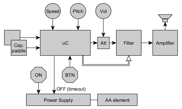
So here is the block diagram:

(functional_diagram.png)
Volume control potentiometer is placed before filter because I wanted to eliminate redundant buffer cascade between filter and amplifier load to filter has influence on its characteristics. Besides the PCB topology became more balanced. Controlling of volume by PWM settings is not a good idea since filter is not perfect and it is better to minimize amount of harmonics of initial signal.
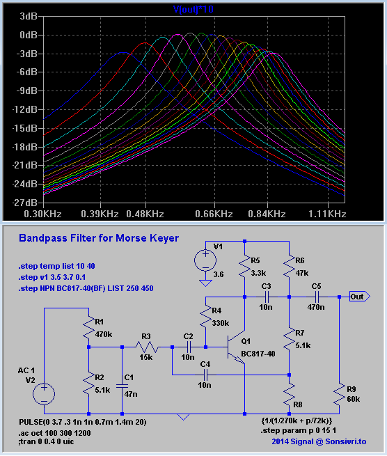
The first guess (with success) how to control filter was to change pull-down resistance by open drain outputs of controller. As the base for the filter I took one with a phase shift feedback circuit similar to phase shift oscillator. Actually I found widely replicated circuit used in colour organ and made some modifications. I can not find the origin to reference it here. Instead some links to followers (just pictures, because all sites are not in English):
http://mozgochiny.ru/wp-content/uploads98983jkhdkjf9873/2011/11/6f43866656.pnghttp://umup.ru/sites/default/files/images/122_1.JPGhttp://pro-radio.ru/user/uploads/212680.jpgFortunately there is an area in multidimensional space of resistors values where adjustment of one pull-down impedance causes central frequency to run through octave with gain difference about 3 dB and with suitable bandwidth.

(phase_shift_filter.png)
R1R2 divider keeps level of signal low enough for lower non-linear distortions and eliminates influence of Volume control potentiometer on impedance R2|C1 and consequently on filter characteristics. R8 is a combination of binary weighted admittances connected to ground by uC port pins. Here four OD pins are used. R6 was added for positive offset on uC pins. R9 is an equivalent of input resistance of next cascade. C1 slightly improves suppression of high harmonics and (nice to think) protects low level input from noise. Temperature stability is quite good, while dependance on transistor gain is significant. Darlington solves this problem completely, but for single unit production calibration is anyway needed, so minimalism won.
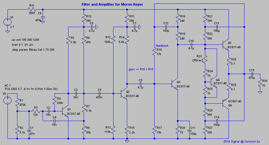
Although an amplifier could be integral in little SOIC-8 package I decided to make it with discrete transistors for earlier mentioned reasons.

(filt_amp.png)
AB-class amplifier works on a 16 Ohm load through coupling capacitor. For better power efficiency to increase output swing the bootstrapping is used: C12,C13,C14. Q4 makes bias for Q5Q6 voltage follower stage. C11 and a feedback R16 makes input impedance of Q3 stage very low (Q3 base is virtually a fixed point) so current amplifier/buffer Q2 stage works as voltage to current converter. Gain from Q2 to R30 is mainly defined by R16/R15 ratio similar to inverting op-amp circuit.
R28, R29 were expected to be redundant here but were placed to test actual influence. Finally 0.1 Ohm resistors were placed just for fun dissipated power is so low that idle current is stable even with zero Ohm.
Increasing R23 will lower nonlinear distortions but in practice with chosen loudspeaker and actual quality of filtration I can not hear any difference so zero Ohm value is used to lower power consumption.
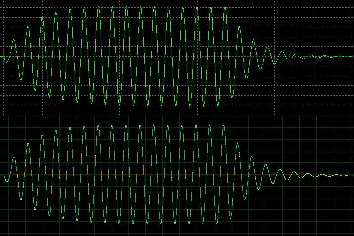
Simulated and captured waves look pretty similar:

(simulated_vs_captured.png)
To get subjective impression the wav-file is attached. There are several portions of pure sine-wave modulated at zero-crossings by square envelop (marked by =) and signal captured from output of represented device (marked by ~) : { =F ~F ~F~ =M ~M ~m ~o }. ~F~ is a copy of ~F that was filtered in audio editor by the similar 2-order bandpass filter (~130 Hz @ 3 dB). Recordings was made with unattached load only last o with attached 16 Ohm loudspeaker. Last portion of recording was made with volume set to the half that slightly lower even harmonics that is indistinguishable by ear.
Measured level of harmonics (volume at max, w/o load, fundamental tone 0 dB):
-44, -34, -71, -42, -61, -53, -70, -53, -68, -62, -76, -62, -76, -68, -92, -68 (dB).
Zip-file also contains LTspice schematic asc-files that correspond to given snapshots.
Purity of the derived sine-wave is not perfect but could be acceptable for fast speeds edges mainly mask weak harmonics. Still not perfect edges slightly audible claps. Narrowing pass band or better use two filters in sequence solve this problem, but who need it? I, personally, consider quality as acceptable, approach as efficient and experiment as successful. Enjoy.


