The Godfather talking
This is god damn my place! Capisci?
Sonsivri
 
*
Welcome, Guest. Please login or register.
Did you miss your activation email?
November 27, 2024, 01:50:27 01:50


Login with username, password and session length


Pages: 1 [2]  All
Print
Author Topic: USB Brenner 8  (Read 34356 times)
0 Members and 1 Guest are viewing this topic.
eSilviu
Newbie
*
Offline Offline

Posts: 34

Thank You
-Given: 4
-Receive: 7


« Reply #25 on: January 23, 2007, 12:02:52 12:02 »

hey, no problem
noo need to say "sorry"

i tought everyone is as advanced as me Grin
even so, i'm far away from "perfect"

any-way: in every application that you made, it's better to check twice before powering the sistem
Logged
rinderpest
Junior Member
**
Offline Offline

Posts: 41

Thank You
-Given: 23
-Receive: 11

All machines are amplifiers


« Reply #26 on: January 30, 2007, 10:36:27 22:36 »

This for anyone who is struggling to get an 18F2550 programmed with firmware for this Brenner programmer. I used a JDM2 type programmer which I built on breadboard.
here is a link to a _very_ easy to build JDM2 serial type programmer:
[link]http://www.instructables.com/id/EN28KZDDYVEP286GRI/?ALLSTEPS[/link]
You can build it on breadboard to save money; you will probably have all the parts lying around. If not they wont cost more than £2. You also need, of course, a serial port. Laptop will probably not work. USB>Serial will also not work. New PCs often have weak ports, dig out an old PentiumII!
Here is another circuit:
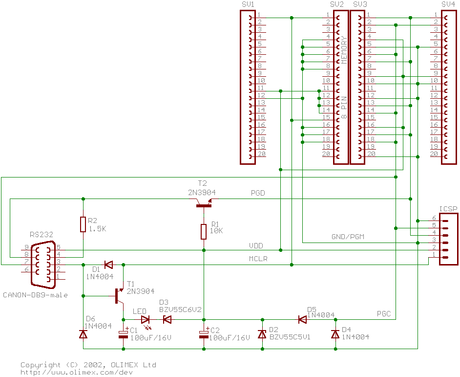
The names of the signals ie MCLR, PGC etc should show you where to connect them to your PIC. If in doubt refer to the datasheet from Microchip.
ICProg works well with this programmer but doesnt support 18F2550 so use WinPIC from:
[link]http://www.qsl.net/dl4yhf/winpicpr.html[/link]
Its free.
With the tools above, and less than 10 cheap components that could even be taken from a dead TV or radio, anyone can program the 18F2550 for the sprute.de firmware.
Good luck guys, it worked for me.
Logged

Experimentum solum certificat in talibus. 
     Experiment is the only safe guide
eSilviu
Newbie
*
Offline Offline

Posts: 34

Thank You
-Given: 4
-Receive: 7


« Reply #27 on: February 02, 2007, 11:28:19 11:28 »

With the tools above, and less than 10 cheap components that could even be taken from a dead TV or radio, anyone can program the 18F2550 for the sprute.de firmware.
Good luck guys, it worked for me.

what about this programmer?!!!!!


simple, but you must power pic with 5+ from an other circuit (not from computer!!!)
resistors will limit the current

it is configured as JDM programmer in winpic

http://home.vrweb.de/~lotharstolz/stolz.de.be/lvpc/index.html

Logged
rinderpest
Junior Member
**
Offline Offline

Posts: 41

Thank You
-Given: 23
-Receive: 11

All machines are amplifiers


« Reply #28 on: February 10, 2007, 02:07:52 02:07 »

I tried one of those type last year. It worked, kind of, with older 16F series. No-go with any 18F.
I agree your circuit is simpler/cheaper but the ones shown below are tested to work on 18F2550 and cost almost nothing.
Did you  manage to program an 18F2550 with the circuit you posted? If so what PC did you use?
The type of serial port in your machine has quite an effect on success.
Logged

Experimentum solum certificat in talibus. 
     Experiment is the only safe guide
eSilviu
Newbie
*
Offline Offline

Posts: 34

Thank You
-Given: 4
-Receive: 7


« Reply #29 on: May 10, 2007, 03:30:14 15:30 »

Software was updated.
No freeze now while writing pic.
works great with hardware version posted in this forum. (sprut has make some changes in schematic posted in his web-page; i tested the new schematic, but i was getting to often "pic not recognized"). so i will stay on old scematic.

cheers!
Logged
charudatt
Active Member
***
Offline Offline

Posts: 111

Thank You
-Given: 53
-Receive: 70


« Reply #30 on: July 08, 2007, 08:30:22 08:30 »

Is there an english manual for this programer. I built one and its working a little funny. It sometimes recognizes and sometime it does not.

I believe you have to do some setting of the Voltage.

Please help.

regards
Logged
Unhappy
Senior Member
****
Offline Offline

Posts: 282

Thank You
-Given: 1005
-Receive: 101


« Reply #31 on: July 09, 2007, 03:16:13 03:16 »

Yes Friend Silviu why not post the files with Drawings and firmware if any
Logged
Vague
V.I.P
Junior Member
*****
Offline Offline

Posts: 51

Thank You
-Given: 699
-Receive: 29


« Reply #32 on: July 16, 2007, 02:15:20 14:15 »

Here is a rough translation of the calibration method. i found with my brenner8 all I had to change was the Zener voltage.

The calibration of the Brenner8
Author: Sprut
Revision: 28.07.2006
 After the Brenner8 was finished developed, which got tax PIC the correct firmware burned and to which USB driver was furnished, those must Programming voltage production of the burner to be still calibrated. An uncalibrated Brenner8 can destroy a PIC within a short time! In particular if as diode D1 is a Shottky type ,  a programming voltage of Vpp=25Vcan be produced .  No PIC can survive this!! The Brenner8 produces the programming voltage Vpp with the help of a small Regulator controller. The voltage level can be varied in software. Thus it is guaranteed that each PIC gets the programming voltage optimal for it. This can only work well if the Brenner 8 pic can measure the voltage accurately. The voltage is measured in the Brenner8 by a voltage divider, and also a reference voltage (of a Zener diode) . During the calibration the Zener voltage and the voltage divider relationship are measured.

 Requirements:
• Brenner8
 • US-Burn-software
 •Voltmeters
Preparation
The Brenner8 attached to a PC. US-Burn running in the PC
  In US-Burn the  configuration tab is in „the tab “Pic programming Options”  “Calibration/Test”.
 The calibration takes place in three steps.
 1. Level of the Zener voltage is measured and input to program.
2. The voltage divider relationship is input to the program.
3. Automatic controller level
1. Zener voltage
In the circuit diagram a 3,3V-Z-Diode is used, but typical breakdown diodes have a tolerance of 10%. The actual voltage needs to be measured. The voltage over the breakdown diode D3 is measured with the voltmeter. That Voltage level is then adjusted the  Z-voltage box.  The voltage can be adjusted  between 2V and 4V in 0.01V steps. Click on “apply” to make the change.
2. Voltage divider
The voltage divider for measuring the Vpp voltage consists of the resistances R4 and R5. Its voltage divider relationship is theoretically 3.14. In practice the value can be slightly different. The value can be changed in the field U- divider. The voltmeter is connected  between the cathode from D1 and Vss (alternatively over C5). With the sliding control (in the programming voltage test box) set Vpp approximately… click on the13V box  . (The voltage should be quite high but should not exceed 14V!) The Brenner8 also measures the voltage , and shows its measured value as Vpp . By adjusting the U-more divider  make the voltmeter reading and the Vpp reading approximately the same.
3. Automatic controller level
Finally USBurn must determine the controller action, so that it can adjust to the correct voltage as fast as possible .
Click the offset and gain button. The burner now makes independently all necessary measurements, which takes approx. 6 seconds. Since there can be quite high voltages , no PIC should be in the test socket or the ICSP connected to the burner . In the programming voltage window the calibration can be checked, by clicking on the 10,11,12,and 13V boxes. For the examination of the result one can click now the switching surfaces 10V, 11V, 12V and 13V. The programming voltage should be within 0.3V.The typical adjusting error amounts to approx.
 Finished
The values are stored in usburn.ini and used when the program is restarted.
 
Logged
Pages: 1 [2]  All
Print
Jump to:  


DISCLAIMER
WE DONT HOST ANY ILLEGAL FILES ON THE SERVER
USE CONTACT US TO REPORT ILLEGAL FILES
ADMINISTRATORS CANNOT BE HELD RESPONSIBLE FOR USERS POSTS AND LINKS

... Copyright 2003-2999 Sonsivri.to ...
Powered by SMF 1.1.18 | SMF © 2006-2009, Simple Machines LLC | HarzeM Dilber MC